We supply whatever you want
Engine Exhaust Silencers for Older Locomotives
For Older Locomotives
ABSTRACT:
Mitigating engine exhaust noise from older locomotives is a substantial challenge. The engine noise is broadband, but also includes prominent low-frequency tones that vary with engine speed. There is very little space inside the locomotive, so while a silencer would ideally be as large as possible, it must fit within tight constraints around other locomotive equipment. Many older locomotives have two-stroke engines that are highly sensitive to back pressure and were designed to run with direct ventilation to atmosphere. This imposes tight constraints on the flow resistance that a silencer can introduce, thereby constraining the design options.
This paper presents a successful case study in mitigating engine noise from an older locomotive. A team of Hushpak Engineering, UTS Tech Lab and Acoustic Studio designed, built and commissioned silencers for the C Class locomotives. The paper discusses how the design challenges of space, back-pressure and low-frequency tones were addressed. It also describes how developing the acoustic solution was not enough to deliver a suc- cessful project. The team had also to design and implement an upgraded crankcase ventilation system to maintain correct engine operation with the silencer in place.
This project showed that silencers for older locomotives can be efficient, effective and inexpensive, and highlights a way forward for addressing noise across the fleet of older locomotives that will remain in service for years to come.
Locomotive noise, after wheel squeal, is one of the main noise impacts on communities living near rail lines. This is particularly the case in Sydney which is surrounded by steep inclines where locomotives emit maximum noise levels for extended periods as they haul freight trains along the busy East Coast main lines.
Locomotives on Australia’s standard gauge network are diesel-electric, meaning they have a large diesel engine that drives an alternator which in turn drives electric traction motors to turn the wheels. The exhaust from the diesel engine is the dominant source of noise on these locomotives. The noise is broadband in nature, but includes substantial low-frequency tones (<100Hz) associated with engine firing. Locomotives have eight (8) engine “notches” in which they can operate (excluding idling). Engine speed, and hence the frequency of the tones, increases with engine notch.
This project involved designing an engine exhaust silencer for the C Class locomotives. The primary objective was to reduce low-frequency noise emissions to approximately the levels of modern locomotives. These are de- scribed in the Environment Protection Licenses of the rolling stock operators (NSW Environment Protection Authority, 2020).
1.1 C Class Locomotives
C Class locomotives were manufactured by Clyde Engineering in 1977/78. They are a 3000hp mainline locomo- tive powered by a turbocharged V16 EMD 645-E3 engine. Ten (10) C Class were built, and six (6) are in service with Southern Shorthaul Railroad (C504/5/6/7/9/10).
Locomotive such as C Class are incredibly durable. Even with 40+ years of active service, C Class is expected to remain operational in NSW for at least another decade. They play a key role in delivering low-margin freight services, particularly transporting agricultural produce to ports, which offer insufficient returns and longevity of haulage contracts to support the purchase of new locomotives. By remaining in service, C Class helps to keep hundreds of trucks off NSW’s roads, easing congestion and reducing greenhouse gas emissions.
C Class however, were among the loudest locomotives in mainline operation through Sydney. They were identi- fied by the community as being subjectively loud, particularly emitting high levels of low frequency noise.
2 - NOISE MITIGATION FOR OLDER LOCOMOTIVES
Older locomotives like the C Class were not designed to have silencers. This is particularly challenging for noise control because:
- There is very little space available on the locomotive to accommodate a silencer. The envelope of the locomotive is constrained by loading gauge restrictions imposed by tunnels, older bridges and overhead wiring. A silencer must therefore fit within this outline gauge, along with all the other equipment on the locomotive. In general terms however, the silencer should be as large as possible to improve its acoustic performance because:
The length of the chambers need to approximate the quarter wavelength of the low frequency diesel engine noise, in order to effectively mitigate this low-frequency. The dominant frequencies on C Class are between 30Hz and 100Hz, a wavelength range of between 6m and nearly 20m;
It can accommodate larger expansions in volume, and hence bigger impedance changes (which reflect acoustic energy within the silencer and therefore prevent it escaping as noise), without imposing re- stricter levels of back-pressure; and,
There is more space to accommodate acoustic absorptive material to mitigate high-frequency noise.
- The engine is very sensitive to back-pressure. This is particularly the case for EMD engines which are two-stroke1. This places substantial restrictions on the design of the silencer in order that the operation of the locomotive is not compromised. Excessive back-pressure can:
De-rate the engine, reducing the power that it can produce, and increase both fuel consumption and diesel emissions.
Cause the engine to shut down. Locomotives commonly have systems to protect the locomotive from excessive crankcase pressure. The crankcase on older locomotives is ventilated through the exhaust. Excessive back-pressure can lead to increases in crankcase pressure which trigger these protective systems to shut down the engine.
The C Class was equipped with either a rudimentary silencer or an exhaust stack, neither of which offered sub- stantial acoustic mitigation. Other locomotives of similar vintage to the EMD 645 engine, such as G Class, have a crude expansion chamber silencer. More modern locomotives generally feature a large “coffin” silencer that occupies the entire roof space above the engine. Figure 1 shows the silencers from G Class and 82 Class. While 82 Class is 25 years old, the evolution in silencer size from the 35+ year old G Class is clear. On more modern locomotives, the silencer is larger still.
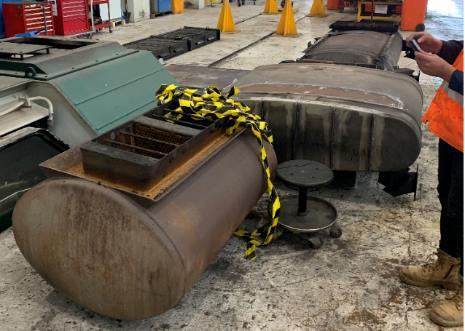
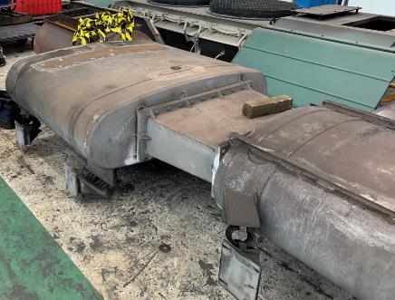
Figure 1 Comparison of crude older silencers, such as on the G Class (left – foreground) and larger coffin silenc- ers such as from the 82 Class (background left, and foreground right). More recent locomotives such as NR, C44aci and GT46C ACe locomotives have even larger silencers than 82 Class.
3- INITIAL INSPECTION
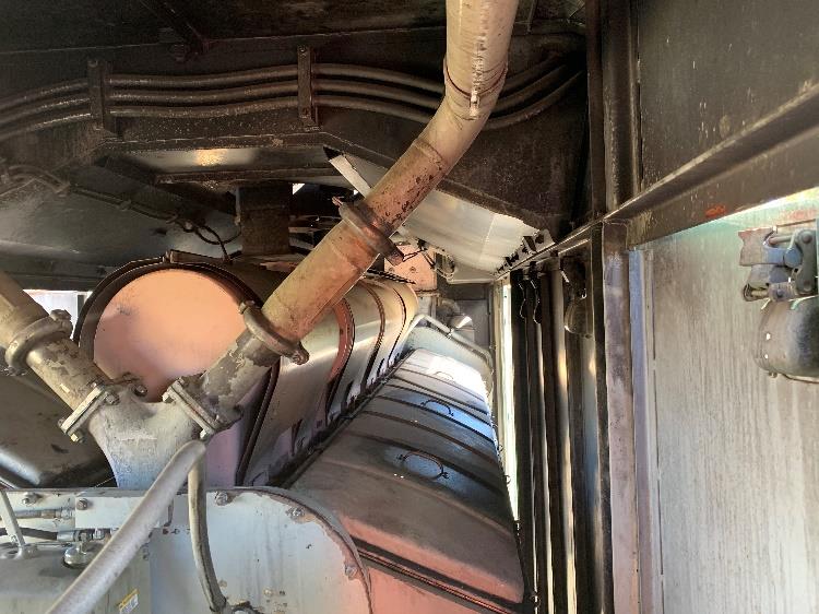
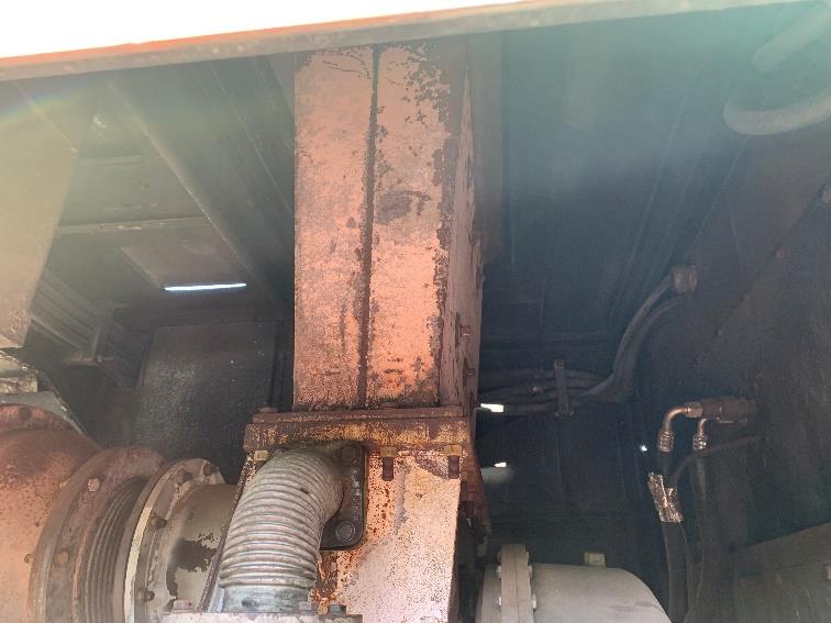
A detailed inspection was conducted on locomotive C509 to identify a suitable location for the silencer and to gauge its size. The interior of the engine bay is shown in Figure 2. The inspection revealed that the dynamic.
1. Older locomotives operating in NSW are almost exclusively equipped with EMD (Electro Motive Diesel), GE (General Electric) or ALCO (American Locomotive COmpany) engines. Both GE and ALCO engines are four-stroke and less sensitive to back-pressure than two-stroke EMD engines.
braking unit was located above the engine, leaving no space for a silencer. The only viable location was immedi- ately atop the turbocharger, where the current exhaust shaft arrangement was located.
This space was tiny in comparison to the size of silencers on modern locomotives. To demonstrate, Figure 3 compares the size of the silencer on modern BRM locomotives (that use a modern version of the same engine as
C Class) with the available space on C Class.
The BRM Class silencer extends the full length of the engine cab (on some other modern locomotives like 1100 Class, the silencer is even larger, extending the full width of the locomotive too, not just the narrower engine cab width). This is possible because on modern locomotives, the dynamic braking unit is smaller and has been relo- cated forward of the engine cab. On the C Class however, and locomotives of a similar vintage, the dynamic brake unit sits atop the engine, leaving only a very small space directly above the turbocharger for a silencer to sit. Noise testing of the locomotive in each engine notch was conducted. This established the baseline noise levels and spectral content to inform the acoustic design. The noise levels of the unmitigated C Class are discussed in Section 7.
With the available space envelope and baseline noise performance quantified, the focus shifted to acoustic de- sign.
4 - ACOUSTIC DESIGN
The first step in the acoustic design process was to identify the target frequency ranges where the baseline noise performance exceeded the objectives – in this case primarily between 31 Hz and 200 Hz. Then, the maximum acceptable pressure drop was determined, which set the dimensions of the air passage and therefore the perfor- mance of the design.
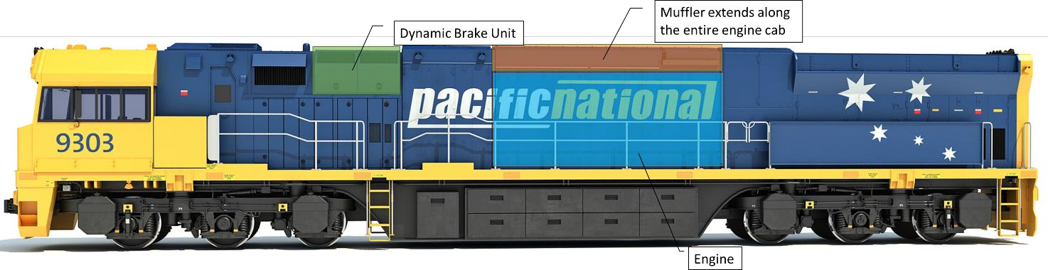
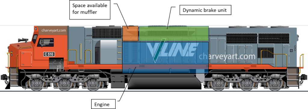
Figure 3 Comparison of the silencer size on a modern locomotive (top) with that of C Class (bottom)
Following identification of the frequency range and maximum silencer dimensions the form of the noise solution was chosen. Dissipative silencers and expansion chambers are common noise control measures used in exhaust systems. However dissipative materials are inefficient below 200 Hz and there was insufficient duct length to apply either silencer type. Quarter wave resonators were chosen as they provide a compact solution at the cost of narrow band attenuation. The effectiveness of this approach was demonstrated in (Croft, Brown, Miller, & Parker, 2014).
Initial silencer design work made use of the 2D finite element method to predict the attenuation of individual quarter wave resonators.
he results showed that at least four resonators would be required to attenuate the frequency range of interest. To fit these into the small available volume required the resonator chambers to be bent around the air passage. Due to this the equation for chamber length, where length = (c)/(4 *target frequency), provided only an initial estimate. The design was optimised through an iterative process whereby the lengths and passage widths were varied. The attenuation of each design was predicted using a 3D finite element model developed in house by UTS Tech Lab.
The design of the silencer itself depends upon a number of compromises. The first of these is the dependence of pressure drop and acoustic attenuation upon passage width. Reducing the dimensions of the air passage within the constraints of the allowable pressure drop will improve acoustic performance. However it will increase the pressure drop and hence decrease the engine efficiency. A balance must be struck.
The performance of the reactive elements also struck a compromise. For a quarter wave resonator the length determines the target frequency, while the cross-sectional area determines the amplitude and bandwidth of the attenuation. For a constant volume there is therefore a choice being made between the length of each reactive element, and thus the target frequency, and its area, and hence the amount of attenuation it provides. To target the low frequency noise required longer resonators, and hence imposed smaller cross sectional areas within the tight space which limited the silencer’s transmission loss.
The aperture shapes were all rectangular to make the most efficient use of the small volume. This included re- moving any rounded corners to maximise the volume and cross section of the resonators and central air passage. Another complication imposed by squeezing the silencer elements into a tight space involved the interaction be- tween the resonators. When in close proximity to each other, the resonators interact which can shift the peak frequency by several Hz and significantly alter the attenuation. The effect of this is observed at the minima be- tween the resonant frequencies, as shown in Figure 4. The red lines show the predicted transmission loss of four silencers, each consisting of a single resonator within a duct. The black line shows the predicted transmission
loss when the resonators are combined into one silencer. A simple model may add together the individual reso- nator’s transmission losses, over predicting performance. However the model for the full silencer shows that each quarter wave resonator may act to reduce or increase the transmission loss of the others.
5- DETAILED DESIGN AND ENGINEERING
The space for the silencer was effectively a rectangular prism directly on top of the turbocharger. The prism could only be a maximum of about 650mm high. The EMD engine turbocharger had a large rectangular outlet connection flange to the exhaust system, requiring the gas flow path up through the centre of the silencer to be a similar rectangular shape.
The detailed design included preliminary 3D models & drawings to establish the external dimensions, noting that the silencer assembly would also have to fit through the roof opening on the locomotive during installation.
The acoustic design necessitated that the rectangular central air passage through the silencer would have to be significantly smaller than the rectangular turbocharger outlet.
With such a short gas flow path through the silencer, there was no length available to fit a gentle transition between the turbocharger outlet and the narrower silencer. It appeared that the sudden step-change in area would generate significant turbulence in the gasflow and generate more back-pressure on the exhaust gas coming out of the engine than would otherwise have been desirable.
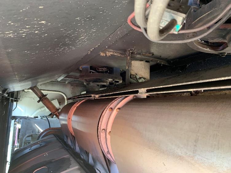
One further complication related to how the engine crankcase fumes were vented. The arrangement included an eductor tube positioned directly into the exhaust just before the turbocharger outlet flange, as shown in Figure 5. The shape of the eductor in the gas flow caused a slight vacuum in the crankcase which in turn drew out the crankcase gases. Unfortunately, this meant that any increase in backpressure at the turbocharger outlet would be reflected back as increased engine crankcase pressure. This could potentially trigger the crankcase pressure protection device and shut down the engine.
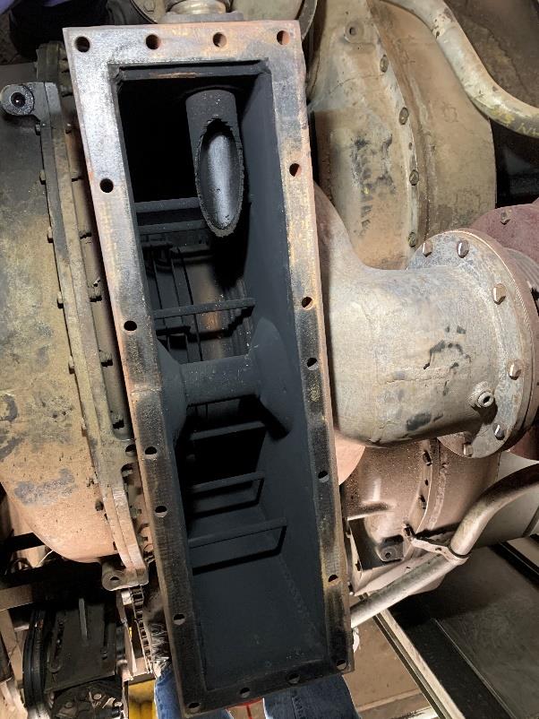
Figure 5 Top view of the turbocharger outlet, showing the eductor tube (left) venting directly into the exhaust flow
The challenge was therefore to design a system with inherent constriction in the exhaust gas flow but at the same time one that creates almost zero back-pressure. A substantial challenge.
One component of the design was a flow-transition device to smooth the airflow between the turbocharger and the silencer. Because of the lack of available length, a tapered constriction was designed to fit down inside the turbocharger housing.
The silencer design also needed to consider the other equipment in the space above the turbocharger. This included the dynamic brake power cables, which can carry thousands of horsepower of electrical energy at more than 1000V, and the airconditioning pipework that ran into the driver cab. This required thermal insulation, in the form of a blanket, to be included in the design.
Three-dimensional solid models of the silencer were then assembled in Autodesk Inventor to design the silencer system and transition and prepare drawings for manufacture. The largest silencer volume now ended up being effectively a pair of different-sized, non symmetric rectangular prisms joined together with the gas flow path up through the centre. The in-turbo transition looked like a pair of wedges fitting well down into the turbocharger outlet throat.
A very short, vaned expansion transition was also designed onto the silencer outlet to try to recover as much of the back-pressure as possible caused by the constriction through the silencer.
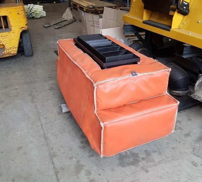
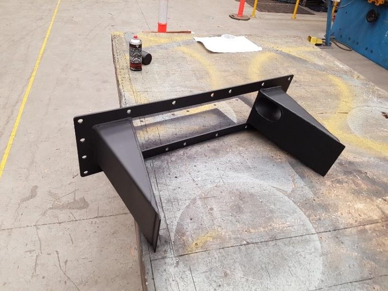
Figure 6 The completed silencer (left) with thermal blanket and flow transition device (right) ready for installation
6- PROTOTYPE TESTING AND CRANKCASE VENTILATION
A prototype silencer was manufactured at Hushpak Engineering in Newcastle and then installed onto C510 at Essbank Siding, Lithgow, with the assistance of Lithgow Railway Workshops.
The silencer was tested in all eight engine notches, with noise measurements recorded at mid-locomotive posi- tions in accordance with AS2377:2002 (Standards Australia, 2002). The silencer performed well until after a few minutes at maximum power (notch 8) when the engine shut down due to excessive crankcase pressure. The noise results were excellent, but the issue of ventilating the crankcase would have to be resolved if the silencer was ever to enter revenue service.
To address this, a venturi type vacuum booster (ejector) system which was used on more recent EMD locomotives was extracted from a nearby locomotive at the Lithgow workshop. This system was originally developed in part to address the challenges of fitting silencers to EMD engines. This ejector was trialled on the C Class, and the crankcase ventilation issue was resolved. We subsequently designed a customised ejector system for the C Class that improved the crankcase ventilation even further, thereby cementing the success of the silencer.
7- NOISE PERFORMANCE
The noise emissions from the upgraded C Class were assessed in accordance with AS2377:2002. The results are compared in Figure 7.
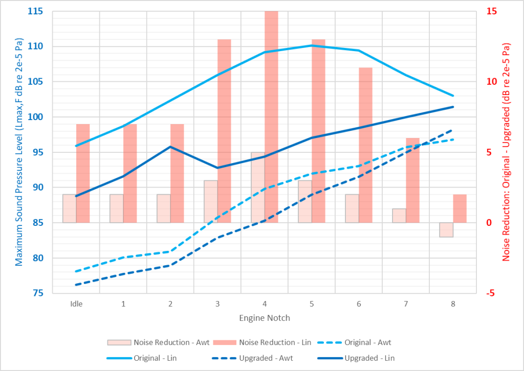
Figure 7 Comparison of the noise emissions from C506 before and after upgrade. Overall levels (blue lines) are compared against the left axis. The right axis shows the noise reduction delivered by the state-of-the-art silencer in each notch (red columns).
The results show reductions in Linear noise emissions of up to 15dB at the most problematic engine notches. A tremendous achievement from such a small silencer
The reductions in A-weighted noise are more modest – up to 5dBA – although these are misleading. In accordance with AS2377:2002, the locomotive was tested under self-load. In this configuration, the full power of the engine was redirected from the traction motors to the dynamic braking grid, effectively converting 3000hp of motive power into heat. This required the dynamic braking system to also operate at full capacity. This is akin to holding the accelerator of a car flat to the floor but at the same time holding the brakes on full. This situation would never occur in revenue service. An alternative way to conduct stationary noise tests is to direct the locomotive power into a load bath, but this was not available at Lithgow.
Under dynamic braking at high engine notches, the fans atop the brake grid (on the top of the locomotive) become a significant noise source in A-weighted terms. As a result, under stationary noise test conditions, the impressive reductions in engine noise are masked by noise from the fans. A better measure of A-weighted noise performance was captured by the Transport for NSW noise monitoring station at Beecroft (Transport for NSW, 2021). For several months in 2021, the upgraded C Class were hauling coal trains past this site. At the same time, the modern CEY Class locomotives were operating on an almost identical service hauling similar wagons. The noise perfor- mance from these trains is compared in Figure 8.
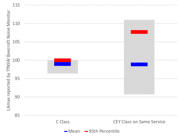
Figure 8 Comparison of the upgraded C-Class (left) and the modern CEY Class locomotives (right) on the same service, as recorded at the Transport for NSW Beecroft monitoring station
The average A-weighted noise levels from the C Class locomotives in revenue service are equivalent to those from the CEY Class, and the maximum noise emissions are substantially lower. This result emphasises the suc- cess of the C Class silencer project in turning one of the loudest locomotives on the network into one that is acoustically similar to modern locomotives.
8- SUMMARY
Mitigating noise from older locomotives is a substantial challenge. With best-practice acoustic and engineering design, and a whole-of-system approach, significant noise reductions can be achieved without compromising the operational efficiency of the locomotive. With many older locomotives likely to remain in service for decades to come, the push for older locomotive to be brought into the modern era in terms of noise emissions will only intensify.
ACKNOWLEDGEMENTS:
The authors would like to thank Chris Jones, and John and Jess Mackie from Southern Shorthaul Railroad, and Paul Selmes and Tim Elderton from Lithgow Railway Workshops for their invaluable assistance with this project.